
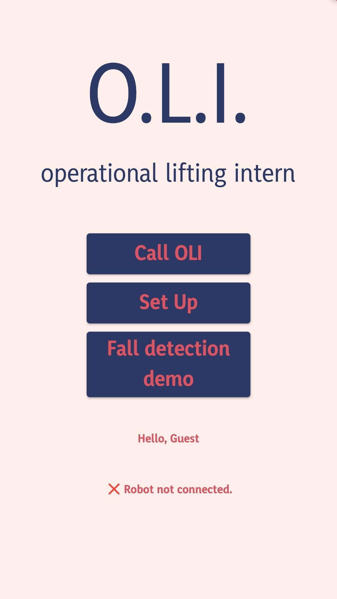
The front-end of the app was built using Flutter. Flutter is programmed in Dart, which is a lightweight programming language. Flutter also allows for modularisation of code, making it incredibly easy to divide tasks and maintain code.
The backend of the app consists of a Flask server that hosts our machine learning model. The Flask API created converts the raw sensor readings into the feature vector and feeds it into the trained model. Flask API, in the real product, will be deployed on the robot in this way to avoid the unexpected latency or even loss of connection if the flask server is deployed by cloud service, and this dose not require connection to the Internet, since both smartphone and robot are able to communicate within the LAN (considering the most of home environment has WiFi).
The fall detection is be treated as a binary classification (fall/normal behaviors) problem in our implementation. We take the public dataset MobiAct (2nd release) as our training set. For the feature engineering, we looked into the previous related researches, and finally decided to take 19 features in total (see the details on GitHub). We compared the performance including the size of the model, runtime and F1-score on different classifiers. We take F1-score rather than commonly used accuracy as main metric is because the dataset is very imbalanced. You can see the final evaluation of the classifier on Evaluation.
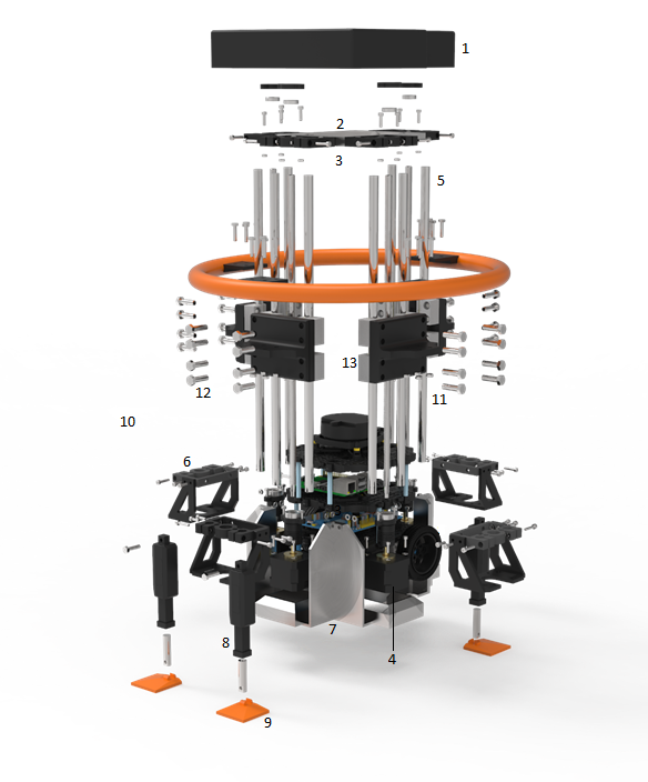
The custom designed external frame surrounding O.L.I. is built to include 2 crucial features - the dynamic support bar which operates via a threaded screw lift system, and the support feet which operate by deploying linear actuators for stability. The components highlighted in orange are those which make contact, either with the user or with the ground. Components numbered 1, 2, 3, and 6 are all 3D printed, since their function is that of holding other components together and providing a minimal amount of support. The rest of the visible frame is comprised of metal components or electronic parts (namely, linear actuators).
Some issues were faced along the way in terms of getting the design to function correctly and reliably. Initially, the support bar was raised and lowered using a motor connected to a pseudo-gearbox, and was also prototyped with a pulley system. The problem with both of these methods is that although the bar was able to move as intended on its own, a very small amount of external pressure would cause the bar to drift down or in some cases, collapse. Raising and lowering the bar with a threaded system has mitigated this issue leading to a much stronger base for the primary contact component of O.L.I.'s frame.
Much of the design stayed the same, and has proven to be resilient under various stress tests.
O.L.I. starts its movement from a random position in an unknown environment and builds the occupancy grid by keeping track of its own position relative to the built map.
We have used SLAM (simultaneous localization and mapping) for this feature and a LDS-O1 LiDAR.
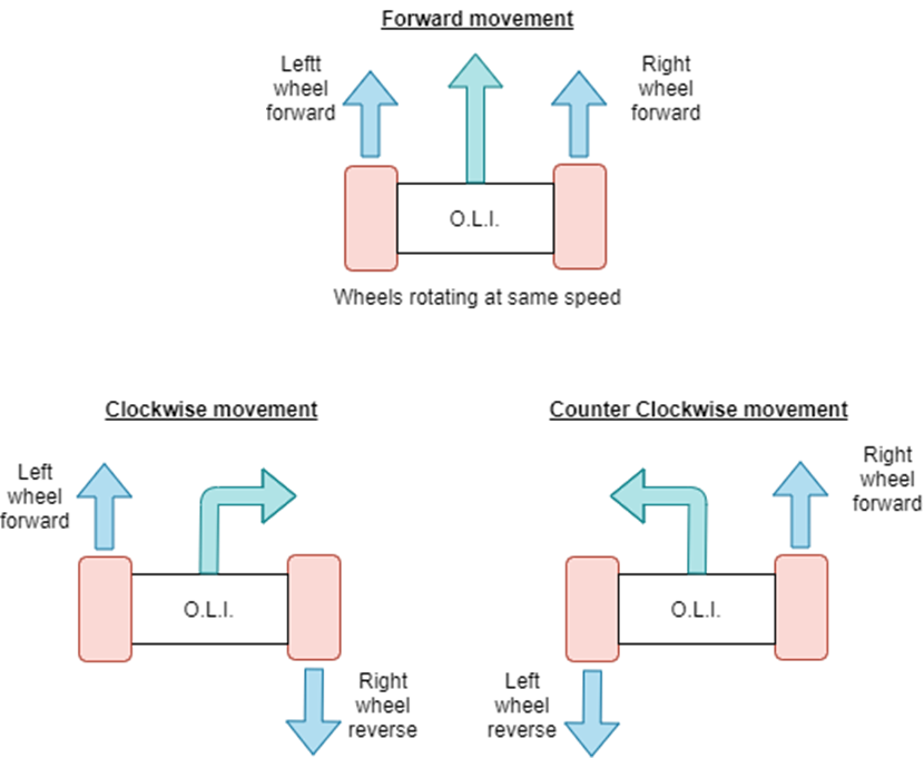
The straight-line movement done by setting the velocity of the motor of the wheels to positive values.
The rotating movement is done by varying the relative rate of rotation of the robot’s wheels. This is possible because the TurtleBot3 is a differential wheeled robot (based on two separately driven wheels placed on either side of the robot body). We get the current location and rotation of the robot then compute an angle and make O.L.I. rotate using that angle in order to face the target point.
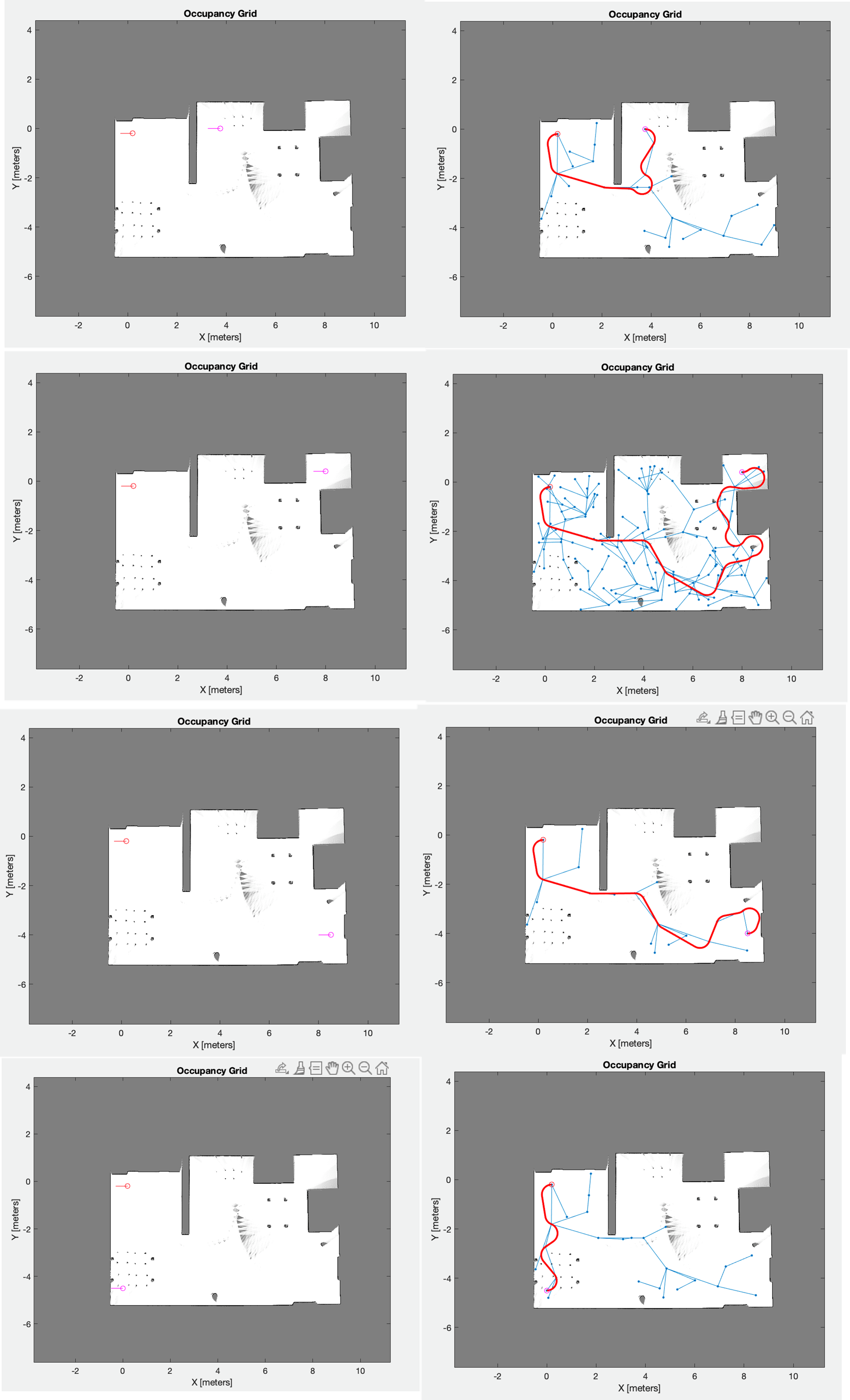
A route-planning feature has been designed using the previously built occupancy grid, and two given points (start and end) in the form of coordinates. The robot's controller can then plan a route that avoids collisions. The algorithm used is rapidly exploring random tree (RTT). In the images below, you can see some examples with visible tree structure (the red dot represents the starting point while the pink dot represents the target destination):
We use a LIDAR sensor (LDS-01) to build the occupancy grid. We selected this LiDAR because its features (3.5 meters range and 360 field of view) are suitable for indoor environment mappings.
Our codebase is present on our GitHub organisation, which you can access here. We appreciate all contributions, so if you feel like you would like to contribute, open a pull request and assign one of the team members to request a review.
© 2021 SDP Group 1 - O.L.I